
Система для испытаний на непрямую восприимчивость к молниям 3ctest LSS 160SM6 и ETS 160MB
Документация производителя:
Когда самолет летит в условиях сильной конвекции, он часто подвергается воздействию удара молнии, который вызывает переходное наведенное напряжение или ток в цепях и кабелях бортового оборудования, такое явление называется непрямым эффектом молнии. Это может привести к тому, что самолет выйдет из-под контроля, может даже привести к возгоранию фюзеляжа и другим серьезным авариям. Из соображений безопасности бортовое оборудование должно быть спроектировано надлежащим образом и полностью протестировано, чтобы обеспечить нормальную работу системы и оборудования с критически важными функциями безопасности и безопасность полета, когда воздушное судно подвергается воздействию удара молнии.
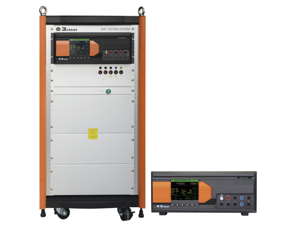
Тестовые системы LSS 160SM6 и ETS 160MB разработаны в соответствии с разделом 22 RTCA / DO-160, LSS 160SM6 способен генерировать сигналы 1,4 и 5A / 5B, а ETS 160MB - сигналы 2, 3 и 6. Оба уровня тестирования находятся в диапазоне от 1 до 5 для тестирования ввода контактов и кабеля тест на связку. Кроме того, тестовая система не только удовлетворяет требованиям к тестированию чувствительности к переходным процессам, вызванным молнией, в MIL-STD-461G CS117, но также удовлетворяет требованиям к уровню импульсной инжекции A / B / C / D EUT в GJB 8848: 2016.
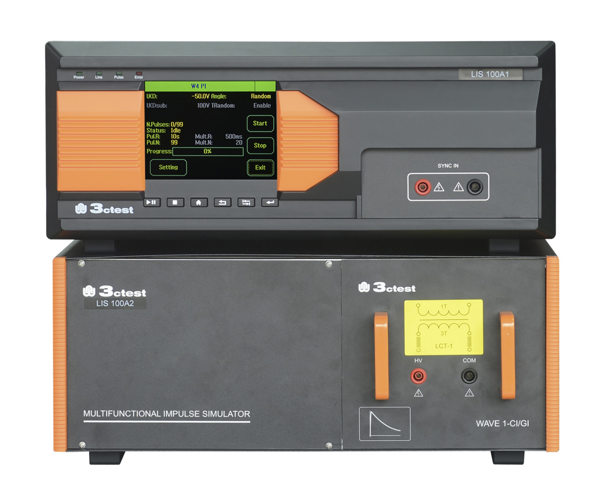
Испытательная система ETS 160MB включает в себя различное вспомогательное испытательное оборудование, облегчающее проведение испытаний, такое как трансформатор связи, устройство блокировки питания, устройство блокировки переходных процессов, контактный инжектор, внешний конденсатор постоянного тока и т. д. Более того, программное обеспечение Corelab также доступно для дистанционного управления, который делает ваш тест простым и удобным.
Особенности:
- Модульная конструкция, модуль формы сигнала является съемным
- Способен генерировать 6 видов сигналов и выполнять тест на ввод штифтов и тест кабельных жгутов
- 5,7-дюймовый цветной сенсорный экран с простым и четким управлением
- Функция фазовой синхронизации в сигнальных штырях и силовых штырях - метод прямого впрыска
- Программное обеспечение Corelab доступно для удаленного управления
Стандарты:
- GJB 8848-2016
- MIL-STD-461G
- AECTP 250
- AECTP 500
- HB 6167.24 (2014)
- RTCA/DO-160G S22
Сведения о реестре СИ
| Номер в Госреестре | Наименование СИ | Обозначение типа СИ | Изготовитель | Срок свидетельства или заводской номер |
|---|---|---|---|---|
| не в реестре | ||||
| Номер в Госреестре | Наименование СИ | Обозначение типа СИ | Изготовитель | Срок свидетельства или заводской номер |
|---|---|---|---|---|
| не в реестре | ||||
| Technical Parameters for LSS 160SM6 | |
| Technical Parameters—Current Waveform 1 Cable Bundle Cable Induction | |
| For tests as per DO-160G S22, MIL-STD-461G CS117(WF2/1) etc. | |
| Coupling Mode | Cable Induction (CI) |
| Output Module | W1 CI/GI |
| Current Waveform 1 | 6.4 μs ± 20 % / 69 μs ± 20 % |
| Single Stroke Output | 50 A ~ 3500 A (-0%~+20%); Output Impedance≤0.5 Ω |
| Multiple Stroke Output | 50 A ~2000 A (-0%~+20%) (first stroke); Output Impedance≤1 Ω |
| 25 A ~ 1000 A (-0%~+50%) (subsequent stroke); Output Impedance≤1 Ω | |
| Number of Subsequent Pulses | 1 ~ 14 (or 1 ~ 30) |
| Interval Time of Subsequent Pulses | 10 ms ~ 200 ms, random mode is available |
| Polarity | positive or negative |
| Number of Test Times | 1 ~ 99 |
| Test Repetition | 30 s ~ 60 s |
| Coupler | LCT- L5 |
| Technical Parameters—Current Waveform 1 Cable Bundle Ground Injection | |
| For tests as per DO-160G S22 etc. | |
| Coupling Mode | Ground Injection (GI) |
| Output Module | W1 CI/GI |
| Current Waveform 1 | 6.4 μs ± 20 % / 69 μs ± 20 % |
| Single Stroke Output | 50 A ~ 3500 A (-0%~+20%); Output Impedance≤0.5 Ω |
| Multiple Stroke Output | 50 A ~ 2000 A (-0%~+20%) (first stroke); Output Impedance≤1 Ω |
| 25 A ~ 1000 A (-0%~+50%) (subsequent stroke); Output Impedance≤1 Ω | |
| The Number of Subsequent pulses | 1 ~ 14 (or 1 ~ 30) |
| Interval Time of Subsequent Pulses | 10 ms ~ 200 ms, random mode is available |
| Polarity | positive or negative |
| Number of Test Times | 1 ~ 99 |
| Test Repetition | 30 s ~ 60 s |
| Maximum EUT Power Supply | AC 230 V / 32 A 50/60 Hz; DC 230 V/32 A |
| Coupler | LCT- L5 |
| Technical Parameters—Voltage Waveform 4 Signal Pins & Power Pins Direct Injection | |
| For tests as per DO-160G S22 etc. | |
| Coupling Mode | Pins Direct Injection (PDI) |
| Output Module | W4 PI |
| Output Impedance | 5 Ω ± 10 % |
| Voltage/Current Waveform 4 | 6.4 μs ± 20 % / 69 μs ± 20 % |
| Output Voltage | 50 V ~ 3400 V (-0%~+10%), (open circuit) |
| Output Current | 10 A ~ 680 A (-0%~+10%), (short circuit) |
| Polarity | positive or negative |
| Number of Test Times | 1 ~ 99 |
| Test Repetition | 30 s ~ 60 s (shortest time depends on output amplitude) |
| EUT Power Supply | Max. 230 V |
| EUT Frequency | Max. 800 Hz |
| Power Blocking Device | Greater than peak value of signal or power voltage (optional) |
| Technical Parameters—Voltage Waveform 4 Cable Bundle Ground Injection | |
| For tests as per DO-160G S22 | |
| Coupling Mode | Ground Injection (GI) |
| Output Module | W4 CI/GI |
| Voltage Waveform 4 | 6.4 μs ± 20 % / 69 μs ± 20 % |
| Single Stroke Output | 50 V ~ 3400 V (-0%~+20%); Output Impedance≥0.5 Ω |
| Multiple Stroke Output | 25 V ~ 1000 V (-0%~+20%) (first stroke); Output Impedance≥0.5 Ω |
| 10 V ~ 500 V (-0%~+50%) (subsequent stroke); Output Impedance≥0.5 Ω | |
| Number of Subsequent pulses | 1 ~ 14 (or 1 ~ 30) |
| Interval Time of Subsequent Pulses | 10 ms ~ 200 ms, random mode is also available |
| Polarity | positive or negative |
| Number of Test Times | 1 ~ 99 |
| Test Repetition | 30 s ~ 60 s |
| EUT Power Supply | Max. AC 230 V / 32 A 50/60 Hz; DC 230 V/32 A |
| Coupler | LVT-1 |
| Technical Parameters—Voltage Waveform 4 Cable Bundle Cable Injection | |
| For tests as per DO-160G S22, etc. | |
| Coupling Mode | Cable Induction (CI) |
| Output Module | W4 CI/GI |
| Voltage Waveform 4 | 6.4 μs ± 20 % / 69 μs ± 20 % |
| Single Stroke Output | 50 V ~ 3400 V (-0%~+20%); Output Impedance≥0.5 Ω |
| Multiple Stroke Output | 25 V ~ 1000 V (-0%~+20%) (first stroke); Output Impedance≥0.5 Ω |
| 10 V ~ 500 V (-0%~+50%) (subsequent stroke); Output Impedance≥0.5 Ω | |
| Number of Subsequent pulses | 1 ~ 14(or 1 ~ 30) |
| Interval Time of Subsequent Pulses | 10 ms ~ 200 ms, random mode is also available |
| Polarity | positive or negative |
| Number of Test Times | 1 ~ 99 |
| Test Repetition | 30 s ~ 60 s |
| Coupler | LVT-1 |
| Technical Parameters—Voltage Waveform 5A Signal Pins & Power Pins Direct Injection | |
| For tests as per DO-160G S22 | |
| Coupling Mode | Pins Direct Injection(PDI) |
| Output Module | W5A PI |
| Output Impedance | 1 Ω ± 10 % |
| Voltage/ Current Waveform 5A | 40 μs ± 20 % / 120 μs ± 20 % |
| Output Voltage | 50 V ~ 3200 V (-0%~+10%) (open circuit) |
| Output Current | 50 A ~ 3200 A (-0%~+10%) (short circuit) |
| Polarity | positive or negative |
| Number of Test Times | 1 ~ 99 |
| Test Repetition | 30 s ~ 60 s (shortest time depends on output amplitude) |
| EUT Power Supply | Max. 230 V |
| EUT Power Frequency | Max. 800 Hz |
| Power Blocking Device | Greater than peak value of signal or power voltage (optional) |
| Technical Parameters—Current Waveform 5A Cable Bundle Cable Induction | |
| For tests as per DO-160G S22, MIL-STD-461G CS117(WF4/5A) etc. | |
| Coupling Mode | Cable Induction (CI) |
| Output Module | W5A CI/GI |
| Current Waveform 5A | 40 μs ± 20 % / 120 μs ± 20 % |
| Single Stroke Output | 50 A ~ 10000 A (-0%~+20%); Output Impedance≤0.3 Ω |
| Multiple Stroke Output | 50 A ~ 2000 A (-0%~+20%) (first stroke); Output Impedance≤0.3 Ω |
| 25 A ~ 1000 A (-0%~+50%) (subsequent stroke); Output Impedance≤0.3 Ω | |
| Number of Subsequent pulses | 1 ~ 14 (or 1 ~ 30) |
| Interval Time of Subsequent Pulses | 10 ms ~ 200 ms, random mode is also available |
| Polarity | positive or negative |
| Number of Test Times | 1 ~ 99 |
| Test Repetition | 30 s ~ 60 s |
| Coupler | LCT- L5 |
| Technical Parameters—Current Waveform 5A Cable Bundle Ground Injection | |
| For tests as per DO-160G S22, MIL-STD-461, CS117 (WF4/5A) etc. | |
| Coupling Mode | Ground Injection (GI) |
| Output Module | W5A CI/GI |
| Current Waveform 5A | 40 μs ± 20 % / 120 μs ± 20 % |
| Single Stroke Output | 50 A ~ 10000 A (-0%~+20%) Output Impedance≤0.3 Ω |
| Multiple Stroke Output | 50 A ~ 2000 A (-0%~+20%) (first stroke); Output Impedance≤0.3 Ω |
| 25 A ~ 1000 A (-0%~+50%) (subsequent stroke); Output Impedance≤0.3 Ω | |
| Number of Subsequent pulses | 1 ~ 14 (or 1 ~ 30) |
| Interval Time of Subsequent Pulses | 10 ms ~ 200 ms, random mode is also available |
| Polarity | positive or negative |
| Number of Test Times | 1 ~ 99 |
| Test Repetition | 30 s ~ 60 s |
| EUT Power Supply | Max. AC 230 V / 32 A 50/60 Hz; DC 230 V/32 A |
| Coupler | LVT- 5 |
| Technical Parameters—Voltage Waveform 5B Signal Pins & Power Pins Direct Injection | |
| For tests as per DO-160G S22 etc. | |
| Coupling Mode | Pins Direct Injection(PDI) |
| Output Module | W5B PI |
| Output Impedance | 1 Ω ± 10 % |
| Voltage/ Current Waveform 5B | 50 μs ± 20 % / 500 μs ± 20 % |
| Single Stroke Output | 50 V ~ 1600 V (-0%~+10%) (open circuit) |
| 50 A ~ 1600 A (-0%~+10%) (short circuit) | |
| Polarity | positive or negative |
| Number of Test Times | 1 ~ 99 |
| Test Repetition | 30 s ~ 60 s (shortest time depends on output amplitude) |
| EUT Power Supply | Max. AC/DC 230 V |
| EUT Power Frequency | Max. 800 Hz |
| Power Blocking Device | Greater than peak value of signal or power voltage (optional) |
| Technical Parameters—Current Waveform 5B Cable Bundle Cable Induction | |
| For tests as per DO-160G S22 | |
| Coupling Mode | Cable Injection (CI) |
| Output Module | W5B CI/GI |
| Current Waveform 5B | 50 μs ± 20 % / 500 μs ± 20 % |
| Single Stroke Output | 50 A ~ 5000 A (-0%~+20%) Output Impedance≤0.3 Ω |
| Multiple Stroke Output | 50 A ~ 2000 A (-0%~+20%) (first stroke); Output Impedance≤0.3 Ω |
| 25 A ~ 1000 A (-0%~+50%) (subsequent stroke); Output Impedance≤0.3 Ω | |
| Number of Subsequent pulses | 1 ~ 14 (or 1 ~ 30) |
| Interval Time of Subsequent Pulses | 30 ms ~ 200 ms, random mode is also available |
| Polarity | positive or negative |
| Number of Test Times | 1 ~ 99 |
| Test Repetition | 30 s ~ 60 s |
| Coupler | LCT ~ L5 |
| Technical Parameters—Current Waveform 5B Cable Bundle Ground Injection | |
| For tests as per DO-160G S22 | |
| Coupling Mode | Ground Injection (GI) |
| Output Module | W5B CI/GI |
| Current Waveform 5B | 50 μs ± 20 % /500 μs ± 20 % |
| Single Stroke Output | 50 A ~ 5000 A (-0%~+20%); Output Impedance≤0.3 Ω |
| Multiple Stroke Output | 50 A ~ 2000 A (-0%~+20%) (first stroke) Output Impedance≤0.3 Ω |
| 25 A ~ 1000 A (-0%~+50%) (subsequent stroke); Output Impedance≤0.3 Ω | |
| Number of Subsequent pulses | 1 ~ 14 (or 1 ~ 30) |
| Interval Time of Subsequent Pulses | 10 ms ~ 200 ms, random mode is also available |
| Polarity | positive or negative |
| Number of Test Times | 1 ~ 99 |
| Test Repetition | 30 s ~ 60 s |
| EUT Power Supply | Max. AC 50/60 Hz 230 V / 32 A; DC 230 V/32 A |
| Coupler | LCT -L5 |
| List of waveform module and test type | |
| Waveform Module | Test type |
| W1 CI/GI | Current waveform 1 – cable bundle cable induction test Current waveform 1 – cable bundle ground injection test |
| W4 PI | Voltage waveform 4 – signal pins & power pins direct injection method |
| W4 CI/GI | Voltage waveform 4 - cable bundle cable induction test Voltage waveform 4 - cable bundle ground injection test |
| W5A PI | Voltage waveform 5A – signal pins & power pins direct injection method |
| W5A CI/GI | Current waveform 5A – cable bundle cable induction test Current waveform 5A – cable bundle ground injection test |
| W5B PI | Voltage waveform 5B – signal pins & power pins direct injection method |
| W5B CI/GI | Current waveform 5B – cable bundle cable induction test Current waveform 5B – cable bundle ground injection test |
| Technical Parameters for ETS 160MB | |
| Technical Parameters—Voltage Waveform 2 Cable Bundle Cable Induction Tests | |
| Coupling Mode | Cable Induction |
| Rise Time | < 100 ns |
| Duration | 6.4 µs ± 20% |
| Test Level for Single Stroke Tests | 50 V ~ 2000 V +20%, -0% |
| Test Level for Multiple Stroke Tests | 50 V ~ 2000 V +20%, -0% (first stroke) |
| 25 V ~ 1000 V +50%, -0% (subsequent stroke) | |
| Polarity | Positive or negative |
| Coupling Transformer | LVT-2 |
| Technical Parameters—Voltage Waveform 3 (1MHz) Signal Pins & Power Pins Injection Tests | |
| Coupling Mode | Pin injection |
| Output Impedance | 25 Ω |
| Frequency | 1 MHz± 20 % |
| Decay Rate of 5th Waveshape | 25% ~ 75% |
| Test Level for Single Stroke Tests | 100 V ~ 4500 V +10%, -0% |
| 4 A ~ 180 A +10%, -0% (short-circuit current) | |
| Polarity | Positive or negative |
| Phase Sync | 0° ~ 359°, resolution 1° |
| EUT Power Supply | Max. AC 230 V, DC ±50 V |
| EUT Power Frequency | 800 Hz |
| Technical Parameters—Voltage Waveform 3 (1 MHz-H) Cable Bundle Cable Induction Multiple Burst | |
| Coupling Mode | Cable Induction |
| Frequency | 1 MHz± 20 % |
| Decay Rate of 5th Waveshape | 25% ~ 75% |
| Output Impedance | ≥60 ohm |
| Coupling Transformer | LVT-2 |
| Technical Parameters—Voltage Waveform 3 (1 MHz) Cable Bundle Cable Induction Tests | |
| Coupling Mode | Cable Induction |
| Frequency | 1 MHz± 20% |
| Decay Rate of 5th Waveshape | 25% ~ 75% |
| Test Level for Single Stroke Tests | 50 V ~ 4500 V +20%, -0% |
| Test Level for Multiple Stroke Tests | 50 V ~ 4500 V +20%, -0% (first stroke) |
| 50 V ~ 2250 V +50%, -0% (subsequent stroke) | |
| Polarity | Positive or negative |
| Coupling Transformer | LVT-2 |
| Technical Parameters—Voltage Waveform 3 (10 MHz) Cable Bundle Cable Induction Tests | |
| Coupling Mode | Cable Induction (CI) |
| Frequency | 10 MHz± 20 % |
| Decay Rate of 5th Waveshape | 25% ~ 75% |
| Test Level for Single Stroke | 50 V ~ 4000 V +20%, -0% |
| Test Level for Multiple Stroke | 50 V ~ 4000 V +20%, -0% (first stroke) |
| 50 V ~ 2000 V +50%, -0% (subsequent stroke) | |
| Polarity | Positive or negative |
| Coupling Transformer | LVT-2 |
| Technical Parameters—Current Waveform 6 Cable Bundle Cable Induction Tests | |
| Coupling Mode | Cable Induction |
| Current Waveform | 5 A ~ 160 A |
| Rise Time | 0.25 μs ±20% |
| Duration | 4 μs ±20% |
| Coupling Transformer | LVT-3 |
| General parameters | |
| Display | 5.7” TFT touch screen |
| Working Power | 220 V,±10%,50/60Hz |
| Fuse | 10 A |
| User’s Memory Space | Infinite (PC) |
| Communication Mode | Ethernet LAN, RJ45 |
| Working Status Indication | LED indication and LCD display on front panel |
| Grounded Connection | Flat earth line |
| Waveform Output Terminal | Banana plug line |
| Dimension | LSS 160SM6: 600 mm(L) x 800 mm(W) x1800 mm(H) (35U rack) ETS 160MB: 445 mm(L) x 690 mm(W) x600 mm(H) (4U×2) |
| Weight | LSS 160SM6: Approx. 150 kg ETS 160MB: 37 kg |
| Ambient Temperature | 15 ℃ ~ 35 ℃ |
| Relative Humidity | 45% ~ 75% |
| Atmospheric Pressure | 86 kPa ~ 106 kPa |