Система для испытаний на непрямую переходную восприимчивость к молниям 3ctest LIS 100A, LIS 100B
Документация производителя:
Когда самолет летит в условиях сильной атмосферной конвекции, он часто подвергается воздействию удара молнии, который вызывает переходное наведенное напряжение или ток в цепях и кабелях бортового оборудования, такое явление называется непрямым эффектом молнии. Это может привести к тому, что самолет выйдет из-под контроля, может даже привести к возгоранию фюзеляжа и другим серьезным авариям. Из соображений безопасности бортовое оборудование должно быть спроектировано надлежащим образом и полностью протестировано, чтобы обеспечить нормальную работу системы и оборудования с критически важными функциями безопасности и безопасность полета, когда воздушное судно подвергается воздействию удара молнии.
Тестовые системы LIS 100A и LIS 100B спроектированы в соответствии с разделом 22 RTCA/DO-160. уровни от 1 до 3 для теста ввода штырей и теста пучка кабелей. Кроме того, испытательная система не только соответствует требованиям к испытаниям на восприимчивость к переходным процессам, вызванным молнией, в соответствии с MIL-STD-461G CS117, но также удовлетворяет требованиям к уровню инжекции импульсов EUT A/B/C/D в соответствии с GJB 8848: 2016.
Тестовая система включает в себя различное вспомогательное оборудование для тестирования, чтобы сделать его удобным для проведения испытаний, например, трансформатор связи, устройство блокировки питания, устройство блокировки переходных процессов, штыревой инжектор, внешний конденсатор постоянного тока и т. д. Более того, программное обеспечение Corelab также доступно для удаленного управления тестированием, что делает ваш тест простым и удобным.
Особенности:
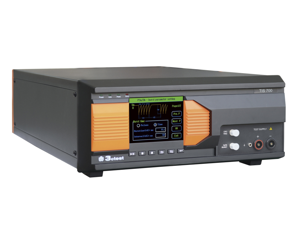
- Модульная конструкция, съемный модуль осциллограммы
- Способен генерировать 6 видов сигналов и выполнять тест на ввод штифтов и тест кабельных жгутов
- 5,7-дюймовый цветной сенсорный экран с простым и четким управлением
- Функция фазовой синхронизации в сигнальных штырях и силовых штырях - метод прямого впрыска
- Программное обеспечение Corelab доступно для удаленного управления
Стандарты:
- GJB 8848-2016
- DO-160G S22
- MIL-STD-461G
- AECTP 250
- AECTP 500
Сведения о реестре СИ
| Номер в Госреестре | Наименование СИ | Обозначение типа СИ | Изготовитель | Срок свидетельства или заводской номер |
|---|---|---|---|---|
| не в реестре | ||||
| Номер в Госреестре | Наименование СИ | Обозначение типа СИ | Изготовитель | Срок свидетельства или заводской номер |
|---|---|---|---|---|
| не в реестре | ||||
| Technical Parameters – LIS 100A | ||
| W1 | ||
| Coupling Mode | Cable Induction (CI) | Ground Injection (GI) |
| Module Selection | Wave 1-CI/GI | Wave 1-CI/GI |
| Current Waveform | 6.4 μs ± 20 % / 69 μs ± 20 % | 6.4 μs ± 20 % / 69 μs ± 20 % |
| Single-Stroke | 25 A – 1000 A +20%, -0% | 25 A – 1000 A +20%, -0% |
| Multiple-Stroke | 25 A – 1000 A +20%, -0% (First stroke); 25 A – 350 A +50%, -0% (Subsequent stroke) | 25 A – 1000 A +20%, -0% (First stroke); 25 A – 350 A +50%, -0% (Subsequent stroke) |
| No. of Subsequent Strokes | 1 – 14 adjustable | 1 – 14 adjustable |
| Time Intervals of Subsequent Strokes | 10 ms – 200 ms adjustable, uniformity mode or random mode | 10 ms – 200 ms adjustable, uniformity mode or random mode |
| Polarity | +, - | +, - |
| Current Coupling Device | LCT-1 | LCT-1 |
| No. of Tests | 1 – 99 | 1 – 99 |
| Test Repetition | 30 s – 60 s | 30 s – 60 s |
| EUT Load Capacity | / | AC 230 V, 16 A, 50 Hz / 60 Hz, & DC |
| W4 | ||
| Coupling Mode | Cable Induction (CI) | Ground Injection (GI) |
| Module Selection | Wave 4-CI/GI | Wave 4-CI/GI |
| Voltage Waveform | 6.4 μs ± 20 % / 69 μs ± 20 % | 6.4 μs ± 20 % / 69 μs ± 20 % |
| Single-Stroke | 10 V – 1,700 V +20%, -0% | 10 V – 1,700 V +20%, -0% |
| Multiple-Stroke | 10 V – 1,700 V +20%, -0% (First stroke); 10 V – 500 V +50%, -0% (Subsequent stroke) | 10 V – 1,700 V +20%, -0% (First stroke); 10 V – 500 V +50%, -0% (Subsequent stroke) |
| No. of Subsequent Strokes | 1 – 14 adjustable | 1 – 14 adjustable |
| Time Intervals of Subsequent Strokes | 10 ms – 200 ms adjustable, uniformity mode or random mode | 10 ms – 200 ms adjustable, uniformity mode or random mode |
| Polarity | +, - | +, - |
| Voltage Coupling Device | LVT-1 | LVT-1 |
| No. of Tests | 1 – 99 | 1 – 99 |
| Test Repetition | 30 s – 60 s | 30 s – 60 s |
| EUT Load Capacity | / | AC 230 V, 16 A, 50 Hz / 60 Hz, & DC |
| W4 | ||
| Coupling Mode | Pin Injection (PI) | |
| Module Selection | Wave 4-PI | |
| Output Impedance | 5 Ω ±10% | |
| Voltage/Current Waveform | 6.4 μs ±20% / 69 μs±20% | |
| Single-Stroke | 25 V – 800 V +10%, -0% (open-circuit voltage); 5 A – 160 A +10%, -0% (short-circuit current); | |
| Polarity | +, - | |
| No. of Tests | 1 - 99 | |
| Test Repetition | 10 s – 60 s (the min. depends on the output amplitude) | |
| EUT Power Sync | Synchronized automatically with AC power peak value or 0°~359° (resolution 1°, tolerance less than 10°) | |
| EUT Load Capacity | AC 230 V, 800 Hz | |
| W5A | ||
| Coupling Mode | Cable Induction (CI) | Ground Injection (GI) |
| Module Selection | Wave 5A-CI/GI | Wave 5A-CI/GI |
| Current Waveform | 40 μs ± 20 % / 120 μs ± 20 % | 40 μs ± 20 % / 120 μs ± 20 % |
| Single-Stroke | 20 A – 2,000 A +20%, -0% | 20 A – 2,000 A +20%, -0% |
| Multiple-Stroke | 20 A – 2,000 A +20%, -0% (First stroke); 20 A – 800 A +50%, -0% (Subsequent stroke) | 20 A – 2,000 A +20%, -0% (First stroke); 20 A – 800 A +50%, -0% (Subsequent stroke) |
| No. of Subsequent Strokes | 1 – 14 adjustable | 1 – 14 adjustable |
| Time Intervals of Subsequent Strokes | 10 ms – 200 ms adjustable, uniformity mode or random mode | 10 ms – 200 ms adjustable, uniformity mode or random mode |
| Polarity | +, - | +, - |
| Current Coupling Device | LCT-1 | LCT-1 |
| No. of Tests | 1 – 99 | 1 – 99 |
| Test Repetition | 30 s – 60 s | 30 s – 60 s |
| EUT Load Capacity | / | AC 230 V, 16 A, 50 Hz / 60 Hz, & DC |
| W5A | ||
| Coupling Mode | Pin Injection (PI) | |
| Module Selection | Wave 5A-PI | |
| Output Impedance | 1 Ω ±10% | |
| Voltage/Current Waveform | 40 μs ± 20 % / 120 μs ± 20 % | |
| Single-Stroke | 25 V – 800 V +10%, -0% (open-circuit voltage); 25 A – 800 A +10%, -0% (short-circuit current); | |
| Polarity | +, - | |
| No. of Tests | 1 - 99 | |
| Test Repetition | 10 s – 60 s (the min. depends on the output amplitude) | |
| EUT Power Sync | Synchronized automatically with AC power peak value or 0°~359° (resolution 1°, tolerance less than 10°) | |
| EUT Load Capacity | AC 230 V, 800 Hz | |
| Technical Parameters – LIS 100B | ||
| W2 | ||
| Coupling Mode | Cable Induction (CI) | |
| Rise Time | < 100 ns | |
| Duration | 6.4 μs ±20 % | |
| Single-Stroke | 25 V – 1,600 V +20%, -0% | |
| Multiple-Stroke | 25 V – 700 V +20%, -0% (First stroke); 25 V – 350 V +50%, -0% (Subsequent Stroke) | |
| Single-Stroke Repetition | 2/1 s @ 25 V, 1/1.5 s @ 1,600 V | |
| Polarity | +, - | |
| High-Frequency Voltage Coupling Transformer | LVT-2 | |
| W3 | ||
| Coupling Mode | Pin Injection (PI) | |
| Module Selection | W3 – 1 MHz | |
| Output Impedance | 25 Ω | |
| Voltage/Current Repetition | 1 MHz ±20% | |
| Attenuation of 5th Stroke | 25% - 75% | |
| Single-Stroke | 100 V – 700 V +10%, -0%; 4 A – 28 A +10%, -0% (short-circuit current) | |
| Single-Stroke Repetition | 2/1 s @ 100 V - 750 V | |
| Polarity | +, - | |
| Phase Sync. | 0° - 359°, 1° step | |
| EUT Load Capacity | AC 230 V, DC ±50 V, 800 Hz | |
| W3 | ||
| Coupling Mode | Cable Induction (CI) | Cable Induction (CI) |
| Module Selection | W3 – 1 MHz | W3 – 10 MHz |
| Voltage/Current Repetition | 1 MHz ±20% | 10 MHz ±20% |
| Attenuation of 5th Stroke | 25% - 75% | 25% - 75% |
| Single-Stroke | 50 V – 2000 V +20%, -0% | 50 V – 1600 V +20%, -0% |
| Multiple-Stroke | 50 V – 2000 V +20%, -0% (First stroke); 50 V – 1000 V +50%, -0% (Subsequent stroke) | 50 V – 1600 V +20%, -0% (First stroke); 50 V – 800 V +50%, -0% (Subsequent stroke) |
| Multiple-Burst | 50 V – 700 V +20%, -0% | 50 V – 800 V +20%, -0% |
| Single-Stroke Repetition | 2/1 s @ 100 V – 750 V | 2/1 s @ 100 V – 1,100 V |
| Polarity | +, - | +, - |
| High-Frequency Voltage Coupling Transformer | LVT-2 | LVT-2 |
| W6 | ||
| Coupling Mode | Cable Induction (CI) | |
| Current Waveform | 5 A-75 A | |
| Rise Time | 0.25 μs ±20% | |
| Pulse Width | 4 μs ±20% | |
| High-Frequency Voltage Coupling Transformer | LVT-3 | |
| General Parameters | ||
| Power Supply Voltage | AC 110 V / 220 V ±10%, 50 Hz /60 Hz ±5% (Default AC 220 V 50 Hz in mainland China) | |
| Max Power | 200 W | |
| Operating Temp. | 15 ℃ - 35 ℃ | |
| Operating Humidity | 45% - 75% | |
| Operating Air Pressure | 86 kPa – 106 kPa | |